https://youtu.be/tXf1xKiKKu0?t=20m35s
In one of the recent MGS5 gameplay videos, there is a moment where the protagonist throws a grenade, only to have their companion AI shoot it into a helicopter that was otherwise almost impossible to take down. It's the kind of over-the-top action we've come to expect from Hideo Kojima, but how would we implement something like this into one of our own games?
There are of course always an enormous amount of ways this can be done. Here, we'll look at just two:
- As a script attached to the helicopter
- As a more generic action available to the companion AI
The key here is to really start thinking about how we would structure the underlying code to give us the building blocks we would need to not only script this event, but many like it. Let's think about the steps involved.
As a script attached to the helicopter
We might want to attach this script to the helicopter if it's a non-generic action that can only occur when the helicopter is present.
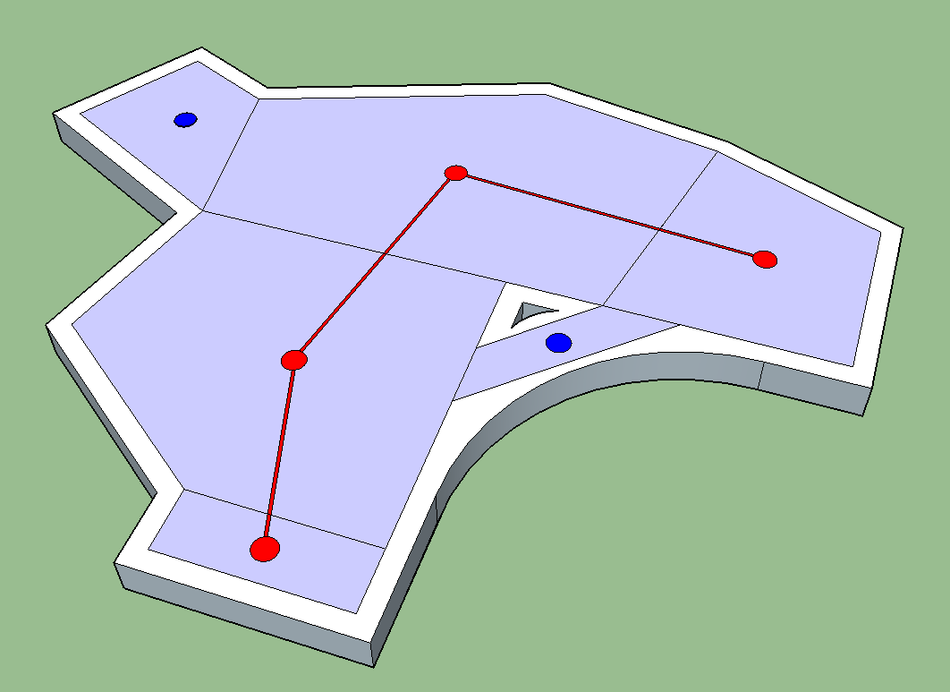
- First we would want a generic way of testing for certain objects based on proximity to other objects, in our case, the helicopter
- We would then want a system that let us query by object type, so again for us, this would be the grendade
- We would probably want to extend this to check to see who threw the grenade, and check for the player as the owner
- Next we would want to check that the grenade was on the same side of the helicopter as our companion AI
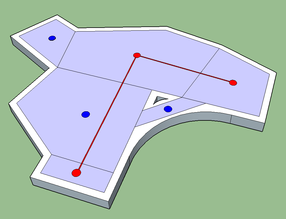
- The companion AI would then be sent a signal to shoot the grenade
- Finally we would add the approprioate velocity to the grenade and destroy the Helicopter
With this piece of logic we could write an event that would happen naturally if the player ever ended up in this particular situation. More importantly though in writing generic functions to let us query for objects, owners, positions and so on, we give ourselves the ability to script more events like this, that are equally as unique, very quickly.
Maybe we could make it even more generic though. Let's take another approach.
As a more generic action available to the companion AI
In all honesty it might be a better idea to code this as a generic action that the companion AI possesses, so that they can use this on multiple types of enemies. This is now not then a scripting task, but it's still good to think about the steps involved.
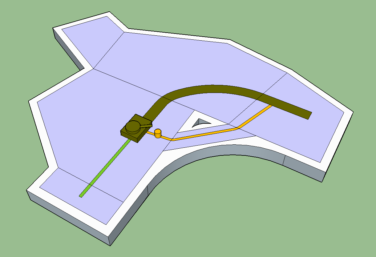
Here we would probably want the AI to be constantly positioning in a way that is helpful for the player, again this will be something core to the way the AI is coded so is not really a scripting task. You can see in the demo that the AI jumps next to the player before jumping away, signposting her position so that they can better choose to use the action. Then, when a grenade is thrown, the AI will perform a cone check to see if the grenade is going to move in between her and an enemy, and if it does, shoot it towards them. This will give the AI the ability to shoot multiple objects at multiple enemies given the right positioning, and in doing so may result in some interesting opportunities for emergent gameplay.
In actual fact there is an extra step in the video - the player actually asks her to perform this action, but it's not really relevant to the core of the explanation.